Dynamic Programming
- Nikhil Paresh Chirag Payas

- Jun 14, 2020
- 6 min read
What is dynamic programming?
Dynamic programming is dividing a bigger problem into small sub-problems and then solving it recursively to get the solution to the bigger problem.
Dynamic programming was developed by Richard Bellman. It is used in computer programming and mathematical optimization. Therefore, it has wide applications in domains ranging from automotive to economics.
DP for HEV energy management
Dynamic programming is quite a popular method for Hybrid electric energy management because it gives the global optimal solution. However, because of its dependence on entire drive cycle information beforehand and high computational burden, it is not real-time implementable. But it is used widely to produce benchmark solutions for the problem. And the results produced by other methods are compared with that of DP results to analyze how optimal the other methods are.
HEV energy management :
The problem of HEV energy management is simple. For a demanded driver request, the torque/power split between the ICE and the motor has to be calculated. The power split is calculated such that it achieves a specific goal at the end of the drive cycle. The specific goal is generally minimization of fuel consumption together with a reduction of emissions or either or both of the previous goals are augmented with ride comfort objectives.
Instead of going through DP equations for optimal control and then explaining them, we would directly implement DP for HEV energy management for P2 topology. To know more about different topologies used in hybrid vehicles, click here.
Below is a step by step tutorial for using DP for P2 hybrid to achieve minimum fuel consumption. The code is written in MATLAB which can be easily adapted to python or any other programming languages.
In the example below, the control variable is chosen as power from the battery (P_batt) and state variable as a state of charge (SOC) of the battery. The cost-to-go function is fuel consumption. And the value function V_k(SOC_k) is minimum cost-to-go from step k to N. To know more about cost-to-go, value function, and other terms used in DP, click here.
We also assume that the motor efficiency is 100% and therefore, power withdrawn from the battery is transferred in full amount on the transmission. The battery open circuit voltage is also considered constant throughout the drive cycle which is an ideal case.
Step 1: Load the drive cycle
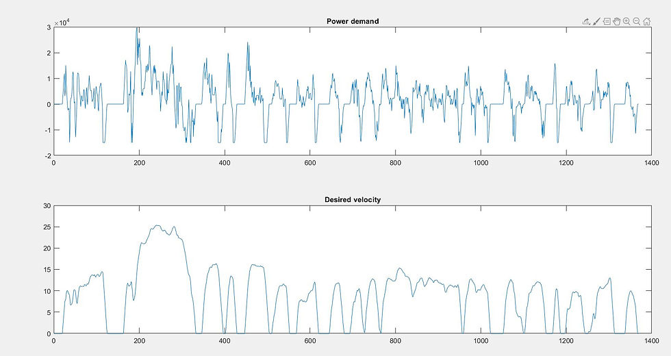
Here, we use the standard UDDS drive cycle for this example. The drive cycle is already converted into the power demand cycle at the transmission to keep things simple. We want to split this power demand between the engine and electric motor such that the fuel consumption is minimum at the end of the drive cycle.
load('UDDS_drive_cycle.mat')          %load the drive cycle (P_dem,v,t)
ts = 1;                               %time step
N = length(t);                        %length of time vector
P_dem = P_dem*1000;                   %Power demand KW to W
subplot(2,1,1);
plot(t,P_dem)
title('Power demand')
subplot(2,1,2);
plot(t,v)
title('Desired velocity')
It can be seen that maximum power demand is around 30KW which can be provided by the engine along with the combination of motor, whose maximum power outputs are 30 & 15 KW respectively.

The drive cycle is a little short to 1400s. As our time step is 1 sec, we would have to iterate through almost 1400 steps through time vector.
Step 2: Initialize the parameters
Let's initialize the minimum and maximum values for engine power and motor power. All these values are assumed. All the values need to be changed according to the particular value.
fl_wt_en = 0.001; %no. of grams consumed per unit energy consumption
Pe_max = 30000;        % [W] Maximum engine power
Pb_max = 15000;        % [W] Maximum battery power
Q_batt = 18000;        % [As] Battery capacity
U_oc = 320;            % [V] Open ciruit voltage of the battery
SOC_min = 0.3;         % Lower SOC limit
SOC_max = 0.8;         % Upper SOC limit
Li-ion battery is widely used in HEV. And the Li-ion batteries are highly inefficient at very low and very high SOC limits. Therefore, SOC has to be limited between some lower and upper values which are here of course assumed.
Step 3: Form a SOC grid
Here we would discretize the SOC values. These values would further be used to calculate energy consumption at each SOC value and the SOC value which gives minimum energy consumption would be selected at each time instant.
SOC_grid = linspace(SOC_min,SOC_max,80)';   %SOC grid
ns = length(SOC_grid);
Step 4: Finding optimal power demand for the motor
So this is the step where we would apply dynamic programming to determine the optimal power output from the battery at every SOC value in the grid such that the fuel consumption is minimum at the end of the drive cycle.
First, the cost value function is initialized. Here I have initialized it to zero, the value doesn't matter the dimensions are important as we use it in the interp1 function later on. The upper loop iterates through time vector from end to start. We would add our cost-to-go function at each time instant to our value function. Power from the battery is chosen such that the resultant value function is minimum. Therefore, when we would reach at time step 0, we would have battery power values which reduce the overall fuel consumption.
V = zeros(ns,N);            %Value function
V(:,N) = 0;                 %Boundary condition
for i = N-1:-1:1            %Iterate through time vector
    for j = 1:ns            %Iterate through SOC grid
     lb = max([(((SOC_max-SOC_grid(j))*Q_batt*U_oc)/-ts),-Pb_max, P_dem(i)-Pe_max]);          %lower bound P_batt
     ub = min([(((SOC_min-SOC_grid(j))*Q_batt*U_oc)/-ts),Pb_max, P_dem(i)]);                 %Upper bound P_batt
     P_batt_grid = linspace(lb,ub,250);      %P_batt grid
     P_eng = P_dem(i) - P_batt_grid;         %P_eng at for P_batt_grid
     c2g = (ts*fl_wy_en*P_eng)./(eng_eff(P_eng)); %costtogo
     SOC_next = SOC_grid(j) - (ts .* P_batt_grid ./ (Q_batt*U_oc));
     V_nxt = interp1(SOC_grid,V(:,i+1),SOC_next);
     [V(j,i), k] = min([c2g + V_nxt]);
     u_opt(j,i) = P_batt_grid(k);
    end
end
The terminal cost is initialized to zero for all SOC values. At every time step, we iterate through all the SOC grid. Then we find the lower bound and upper bound on battery power. At any given time in P2 hybrid, the lower bound for battery power would be maximum possible power it can be fed with or the power maximum power engine can provide while also fulfilling the power demand or maximum power battery can take to reach the upper bound on SOC constraint. Similarly, lower bound is determined. Then, the battery power grid is calculated at each time instant and each SOC value in the SOC grid. Now all the discretization is done. Then we go on to calculate the cost-to-go function value for each value of battery power. For each value of battery power, we also determine what the next SOC value would be from the dynamic equation of the battery.
Step 5: Driving the car with optimal power split
Let's make a function to drive the car at an optimal power split. Therefore, the function can be run for different initial SOC to analyze the results.
function [Pb_act,Pe_act,FC_act,SOC_act]=RUNHEV(SOC0,N,SOCgrd,u_opt,Pd)
    SOC_act(1) = SOC0;
    SOC_grid = SOCgrd;
    P_dem = Pd;
    U_oc = 320;
    ts =1;
    Q_batt = 18000;
    fl_wt_en = 0.001;
    for i = 1:N-1
        Pb_act(i) = interp1(SOC_grid,u_opt(:,i),SOC_act(i));
        Pe_act(i) = P_dem(i) - Pb_act(i);
        FC_act(i) = (ts*fl_wt_en*Pe_act(i))/(eng_eff(Pe_act(i)));
        SOC_act(i+1) = SOC_act(i) - ((ts*Pe_act(i))/(Q_batt*U_oc));
    end
end
The only thing left is eng_eff function. So, eng_eff function should output the engine efficiency for particular engine power. Here we assume that we have a mapping between engine efficiency and engine power.
function eff = eng_eff(P_eng)
    a = 5e-08;
    b = -6e-06;
    c = 2.6e-04;
    d = -5.8e-03;
    e = 6.8e-02;
    f = 2.6e-05;
    x = P_eng/1000;                   % W to KW
    eff = a*x.^5 + b*x.^4 + c*x.^3 + d*x.^2 + e*x + f;
end
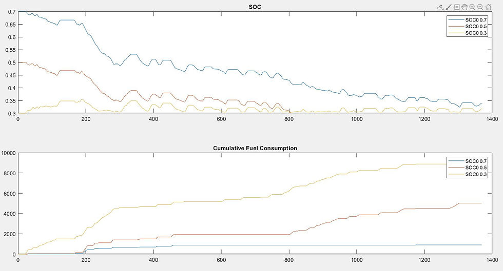
Let us see how is the power divided between the engine and motor for different initial SOCs.
[Pb_07, Pe_07, FC_07, SOC_07]= RUN_HEV(0.7);
[Pb_05, Pe_05, FC_05, SOC_05]= RUN_HEV(0.5);
[Pb_03, Pe_03, FC_03, SOC_03]= RUN_HEV(0.3);
plot(SOC_07)
hold on;
plot(SOC_05)
plot(SOC_03)
title('SOC')
legend('SOC 0.3','SOC 0.5','SOC 0.7')
From the graph, it is clear that when initial SOC is high, more power from the battery is utilized and therefore fuel consumption remains low. If you see, that fuel consumption this drive cycle for say initial SOC equal to 0.7 comes around 9000 gm which may not seem to be realistic is because our assumed value for fuel consumption per unit engine power is very high. Therefore, all the values assumed here are for representation and understanding only. The prime focus here is to understand how DP can be utilized to solve the problem of HEV energy management.

The whole code and the drive cycle can be downloaded here.
This article was written by Paresh Yeole. Please free to contact me for any queries or for maybe pointing out mistakes. Any feedback about the article would be appreciated.


It's a great work, Thanks for your share. And I have a question, about the boundary of the battery power. Why we should set the limit as you do, Could you give us more information. Thanks. Look forward your reply
Can you please write DP equations for optimal control in some other new blog? It will be more helpful for understanding...