Rule Based Energy Management
- Nikhil Paresh Chirag Payas

- Jul 5, 2020
- 3 min read
Updated: Jul 19, 2020
In this article, we would try to understand what is rule-based energy management. Then we would try to develop a very simple rule-based strategy for a P2 Hybrid Electric Vehicle. The goal of the article is not to develop a tuned energy management controller but to understand what kind of rules are used while developing an energy management controller. The controller developed is freely available here. Please feel free to download and modify as per your requirements.
All the hybrid vehicles available in the market today have a rule-based energy management controller. Rule-based controllers are not optimal then why are they so popular? The answer is simple. Rule-based controllers are computationally inexpensive, they are real-time implementable and they don't need any future information. This makes them a popular choice in the energy management world of hybrid vehicles.
A rule-based controller is nothing but a set of rules which can be manifested as if-else statements. These rules are determined by experience, intuition, or also from the results of an optimal controller. A basic rule-based controller is easy to develop. But it gets complex very fast as the no. of rules increases.
Let's develop a simple rule-based controller for a P2 hybrid electric vehicle. The powertrain for a P2 hybrid vehicle is as shown below in the figure :
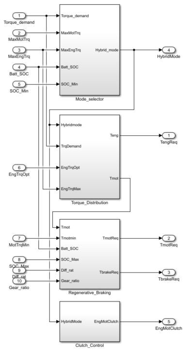
In the figure, ICE stands for the engine, EM stands for an electrical machine. There are two clutches in the powertrain. The operation of the clutch between ICE and EM should be controlled by our energy management controller. Electronic control units (ECU) are used for controlling electrical operations in the car. We assume we have a separate ECU only for hybrid energy management and let's name it Hybrid Control Unit (HCU). HCU would be responsible for torque split between ICE and EM, operation of a clutch between ICE and EM, torque split between EM and friction brakes while braking, and also for ICE ON/OFF operation. We would develop a Simulink block for this HCU.
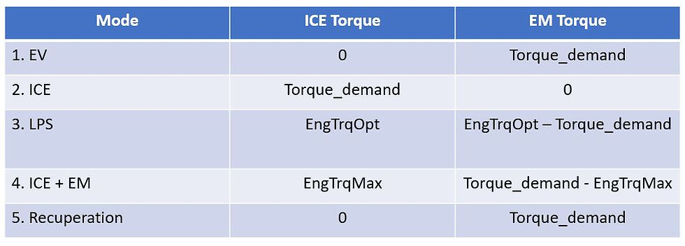
We assume all the relevant signals and parameters are available for the Hybrid_Control_Unit block from a vehicle model. We would develop a rule-based controller that would do torque split. First of all, based on the magnitude of demanded torque from the driver, we would determine the hybrid mode. We have 5 hybrid modes here: 1 - EV mode, 2 - ICE mode, 3 - LPS mode, 4 - ICE + EM mode, 5 - Recuperation mode. The same numbers are used in the Simulink model for the corresponding modes. As the name suggests, EV mode is a fully electric mode. In the ICE mode, all the torque demand is given by the engine only. In LPS (Load point shifting) mode, the electrical machine runs as a generator and charges the battery while engine runs at optimal torque possible at that transmission speed. In ICE+EM mode which is also known as boost mode, the torque demanded is given by electrical machine as well as by engine. In the recuperation mode, the torque is split between the electrical machine and friction brakes. Here series regenerative braking method is used. That is maximum possible regeneration is done and the remaining torque is provided by friction brakes. Here is the flowchart for the algorithm used to determine the mode.
The mode selection algorithm is implemented in the Mode_selector subsystem block. After the hybrid mode is determined, the torque distribution between ICE and EM has to be determined which is implemented in the Torque_Distribution subsystem block. In the table below, the torque distribution for each mode is illustrated.

During recuperation mode, the demanded torque is further divided into friction brake and electrical machine. This is done into Regerative_Braking system block. When battery soc is less than maximum soc, then maximum possible regeneration is done and the remaining torque is given to friction brakes. Else, the whole torque demand is given by friction brakes.
The clutch between ICE and EM is controlled by clutch_control block. The clutch is open during EV and Recuperation mode and is closed in all other modes.
ICE ON/OFF control is not developed here, to encourage the readers to suggest the logic for the same in the comment section below.
Signals such as battery temperature, ICE coolant temperature, power limits on an electrical machine, etc. are not considered here to keep things simple. The controller block looks like this :

As mentioned before, the Simulink model can be downloaded here. Feel free to give a suggestion or point out mistakes in the comment section.
I hope I was able to give a brief idea of how a rule-based energy management controller is developed. The things were deliberately kept simple.
This article is written by paresh yeole. To know more about the author, please visit the about us section.


Can you please write another blog with all explanation of sequential mathematics required for this?